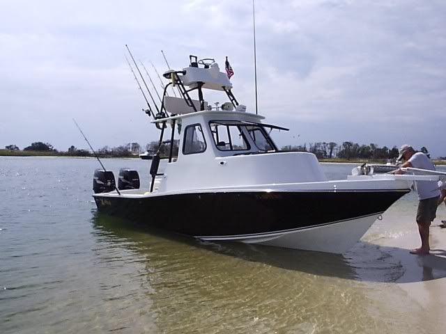
For those that have re-wired their Parkers...

Classic Parker Boat Forum

Help Support Classic Parker Boat Forum:

This site may earn a commission from merchant affiliate links, including eBay, Amazon, and others.

SBH2OMan

Well-known member
Joined
Oct 23, 2010
Messages
552
Reaction score
10
Location
Santa Barbara, CA
As I sit here looking at the forecast of 12' swell and 30+ knot winds over the next 10 days, I'm turning my attention to winter projects, and re-doing the accessory and light wiring is a high priority. Well, pretty much everything needs to be re-wired (or at least re-terminated and cleaned up) except for the engine and dash, which are new.

Main project goals:
1. Move all the battery terminal connections to bus bars
2. Figure out a way to adjust lighting up and down on the dash for running in the pre-dawn hours
3. Eliminate ALL inline fuses with a single breaker & switch panel and a fuse panel for other non-switched accessories.
4. Re-wire electronics to a dedicated battery to eliminate voltage spikes from engine re-starts (causes FF to lock up)
5. Replace cabin lights with LED throughout (pilothouse and berth lights)
6. General clean up.

As I begin compiling my shopping list and planning out this job, I'm curious if anyone has found a good replacement for the original electrical switch panels that have integrated circuit breakers and good lighting?

Also, where is the best place to buy marine quality terminal connectors and wire in small bulk quantities. I get really tired of the 3-packs of butt connectors at West Marine for $4.99...

Does anyone have any other ideas I should be thinking about as part of this project?
 
SBH2OMan":282scrke said:
1. Move all the battery terminal connections to bus bars.
Use the Ancor 'Power Post', do a search on it under my name.

SBH2OMan":282scrke said:
2. Figure out a way to adjust lighting up and down on the dash for running in the pre-dawn hours.
Also see my post under topic name 'DaleH' and you'll see the custom switch panel with backlighting I had made. It did not have dimmable lights.

Just be aware that high quality rheostats for 12VDC are expen$ive! Don't use a cheap Chinese import or it could catch fire and not ALL are limited to the load they carry.

One other tip, I painted all the bulbs in my gauges RED and they work well (readable) whether dark or semi-light out.

SBH2OMan":282scrke said:
3. Eliminate ALL inline fuses with a single breaker & switch panel and a fuse panel for other non-switched accessories.
Why? Fuses are available in more EXACT values than breakers and in an emergency I can remove the fuse and kill the circuit where you may not be able to effectively kill a breaker. Plus breakers are expen$ive and fuses are simple and just plain work. I also have been re-wiring boats for 30-years and have had ZERO fuses blow in any of the boats I have re-wired.

Yes, eliminate in-lines if off a short run to the power buss. But remember fuses or breakers serve to protect the WIRING from burning up and NOT to protect the device. An in-line fuse/brkr protects that short run IF the device itself goes on the fritz and shorts.

SBH2OMan":282scrke said:
4. Re-wire electronics to a dedicated battery to eliminate voltage spikes from engine re-starts (causes FF to lock up)
Look into those BEP Marine battery clusters, they are the bomb!

SBH2OMan":282scrke said:
5. Replace cabin lights with LED throughout (pilothouse and berth lights).
Nice upgrade, did the same, less 1 xenon bulb for reading.

SBH2OMan said:
6. General clean up.[/quote
PM me your email address. I have a DIY wiring tutorial I wrote up when I did mine in 2001 IIRC. But your products in-line and ONLY USE MARINE GRADE components! Buy a good crimper and lots of adhesive-lined heatshrink.

I gotta run, but will add more later!
 
Thanks guys - LOTs of reading material there! :)

Damn warthog, you are the kind of guy I like to buy boats, cars, and motorcycles from once you get bored with them. :mrgreen:

Anyway, a couple of answers/comments:

1. BEP VSR "battery cluster" - yup, put one of those in with the repower last year, along with three new Optimas. LOVE it!

2. RE fuses - yea, I plan to use a combination of breakers and fuses. I just don't want randomly spaced INLINE fuses running separately from each gadget. My issue is ease of access and the ability to quickly and easily find a fuse once (if) it blows. I can tell you that right now with the state of my wiring (two POs that were er, not well-trained on marine wiring) is such that if I suddenly lost power to an important circuit, it could take me hours of tracing with a voltmeter to figure out what went wrong. Thankfully this hasn't happened, but I never want it to.

My plan is to have a labeled panel with AGC fuses for all the electrical accessories, and then a switch/breaker panel to replace the OEM Parker dash-mounted unit. In looking at the factory setup, it appears that each lighting circuit has a single fuse or breaker in the switch panel (e.g. Nav lights, rear bilge, forward bilge, etc). I want the bilge pumps on breakers so I don't have to go searching for fuses in an emergency (if the boat is taking on water, I figure that getting juice to the pumps is more important than the margin of safety afforded by fuses, but perhaps my thinking is wrong).

Lastly, the batteries are currently wired as one for starting, the other two in parallel for house, with a VSR separating them. Even in this configuration, I get voltage drop across the house bank when I start the engine. I'm not sure if this is something wrong with the wiring somewhere (which would not surprise me at all) or if this is normal operation of the VSR. In either case, do you guys have any good suggestions for truly isolating the starting circuit from the house circuit to eliminate voltage drop? As some of you may know, Raymarine electronics (even the newest stuff) is extremely sensitive to very very slight fluctuations in voltage, causing the fish finder to lock up and require a reset.

If I get down the the boat, I'll snap some pix of my current wiring mess so you guys can see the horror I am starting with. :)
 
Damn warthog, you are the kind of guy I like to buy boats, cars, and motorcycles from once you get bored with them. :mrgreen:

I've got one For Sale....:)

http://www.classicmako.com/projects/xshark/

DadsFirsttrip017.jpg
 
I get voltage drop across the house bank when I start the engine. I'm not sure if this is something wrong with the wiring somewhere (which would not surprise me at all) or if this is normal operation of the VSR.

Something is not right.

Start at the batteries and the BEP cluster and wire as per instructions.

http://www.bepmarine.com/media/product/ ... 0805d2.pdf

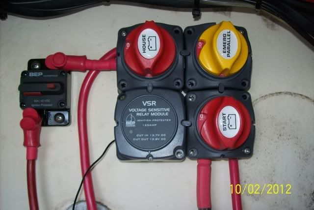
Where the optional fuse is under the switch panel have a 50amp CB close to the BEP Cluster.

That wire actually goes forward to supply power to a Bule Seas 12 gang fuse panel. One of the circuits on the fuse panel will supply power to the switch panel with it properly fused.

Where the optional fuse is at the house battery...I delete it.
 
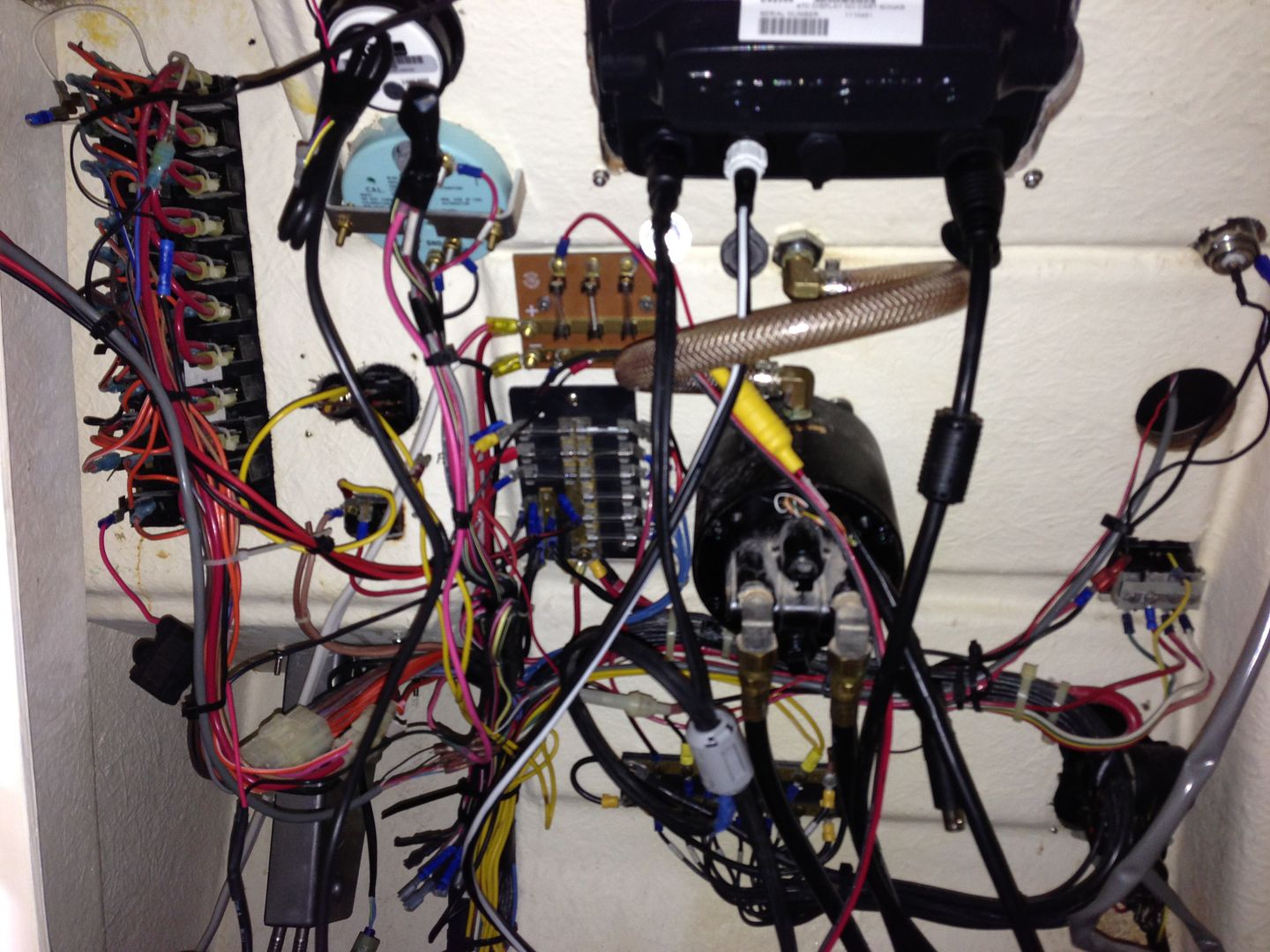
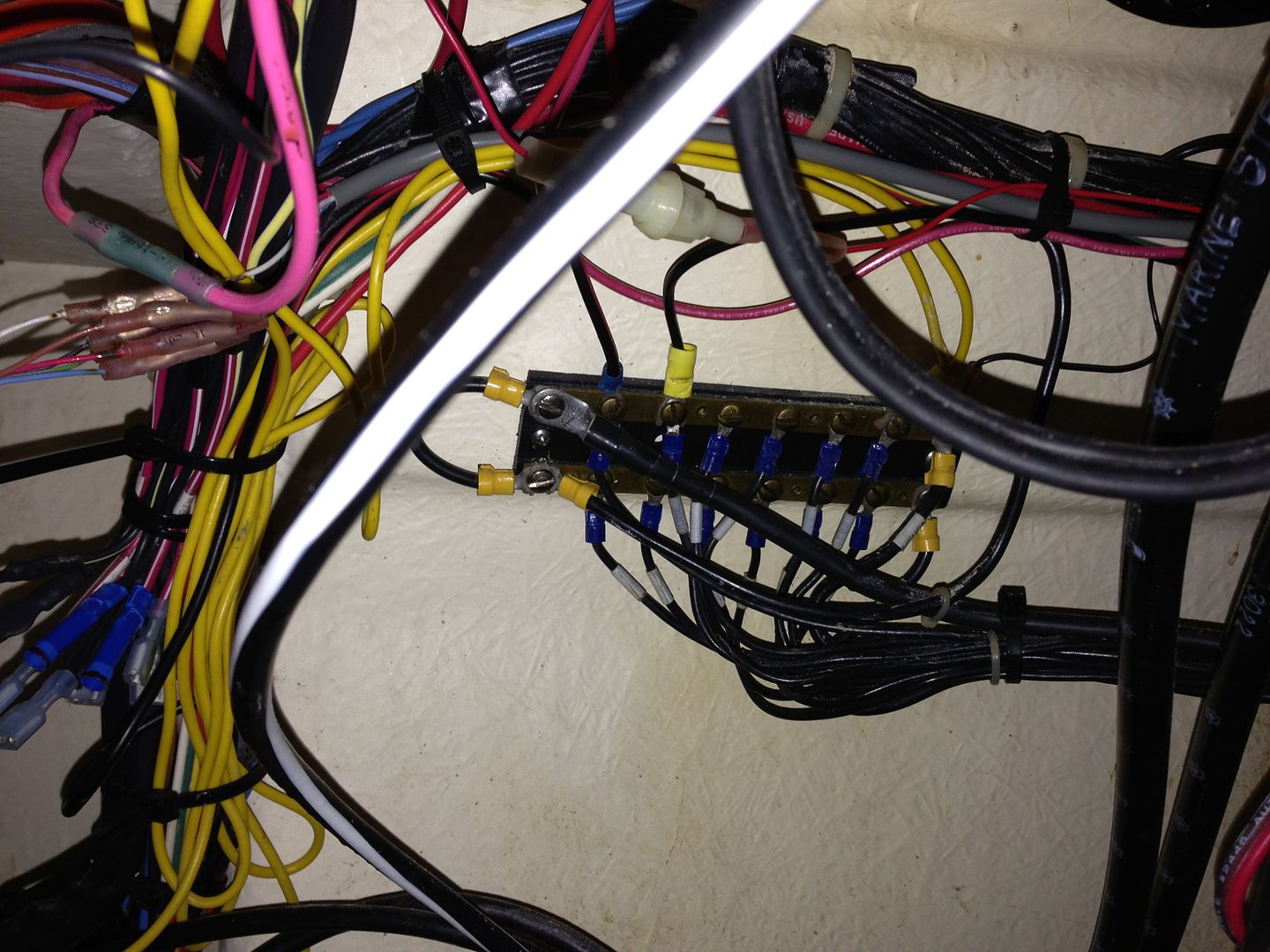
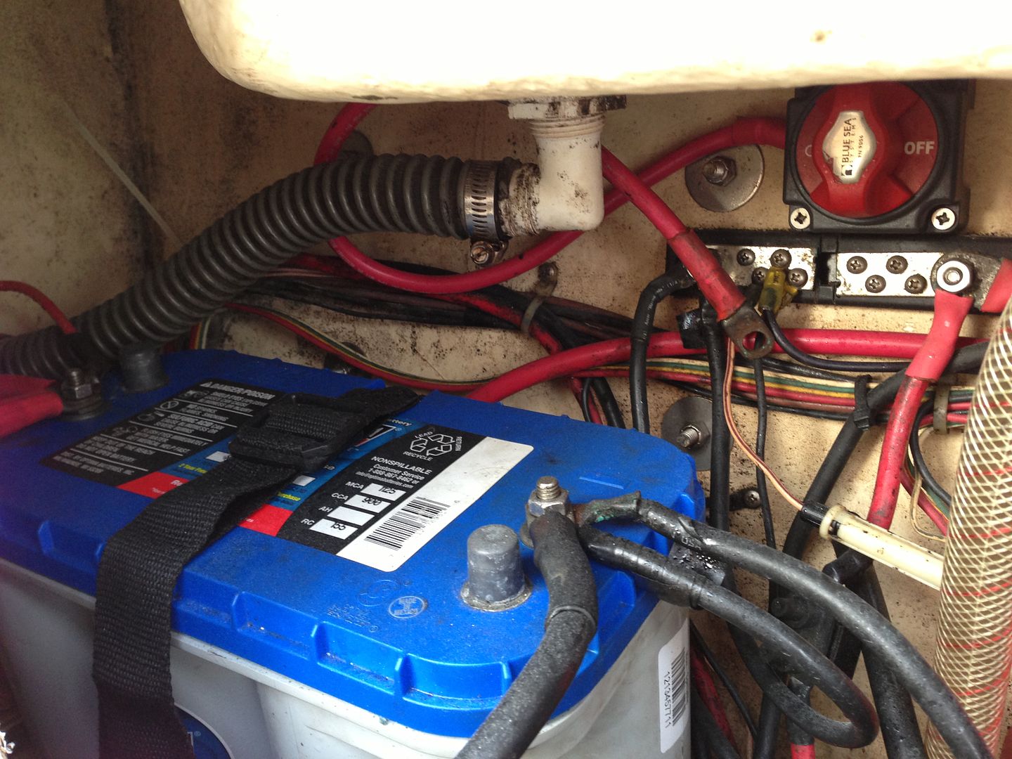
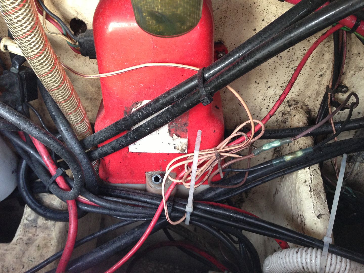
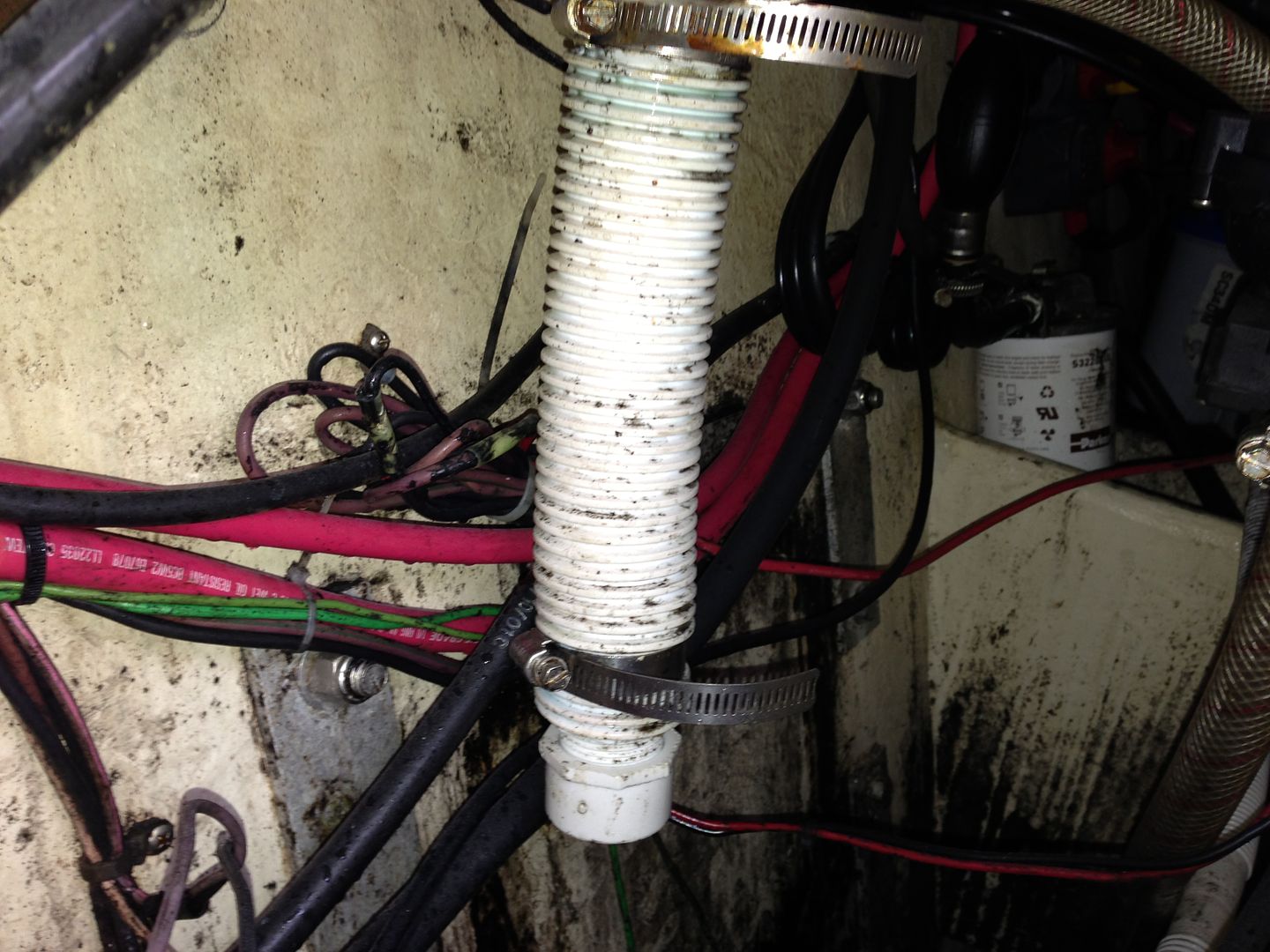
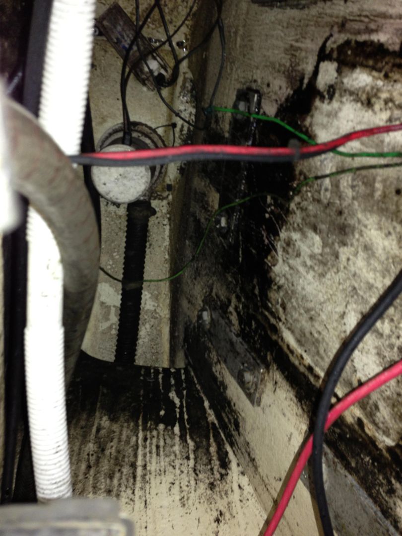
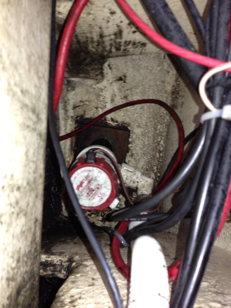
For those of you who want to feel better about the state of your wiring and bilge, I include the following slideshow of horror... (Now that the 2-stroke oil tank is gone, I can finally clean up the bilge!) For those of you with a practiced eye, let the suggestions fly! There's a lot of potential here for improvement. Miraculously, everything works.

Behind the helm:
IMG_0420.jpg


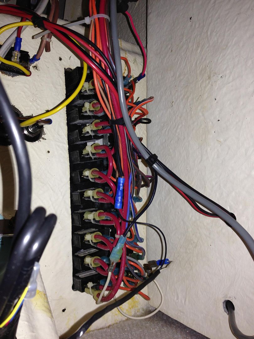
Detail behind the "Parker" switch panel:
IMG_0421.jpg


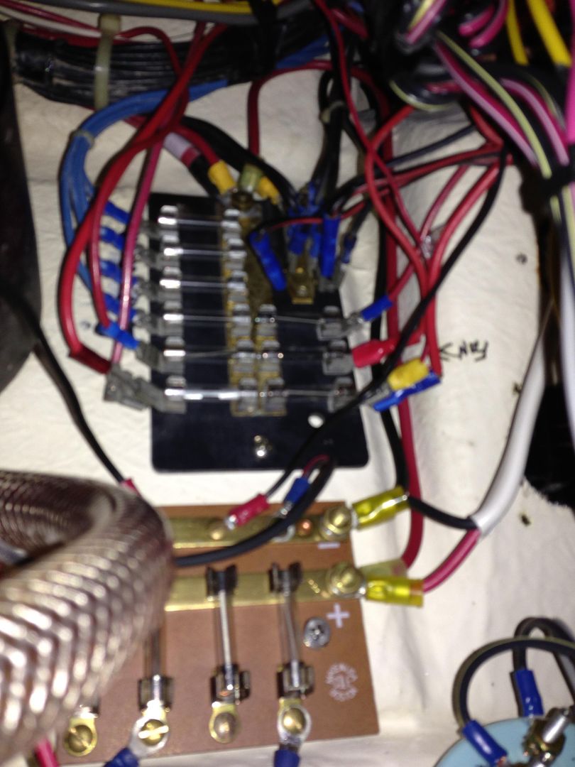
Mis-matched fuse panels without any labels:
IMG_0422.jpg


I have a hard time believing I have this many circuits needing a negative wire (there is another bus bar of negative connections on the other side!)
IMG_0423.jpg


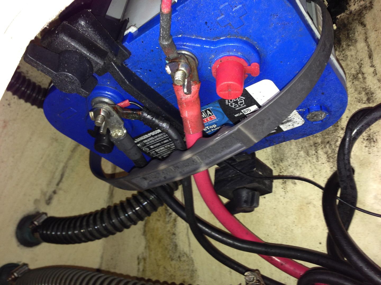
Stbd Side battery (note the switch is leftover from a kicker that has been removed):
IMG_0443.jpg


Dirty Spaghetti around the Boat Leveler pump:
IMG_0444.jpg


More filth and disorganization inside the transom:

IMG_0445.jpg


Unsupported wires all over the place:

IMG_0449.jpg


Scary plastic seacock with cartridge type bait pump (and inlet for washdown):
IMG_0453.jpg


Argh! Wing nuts! :-(

IMG_0456.jpg


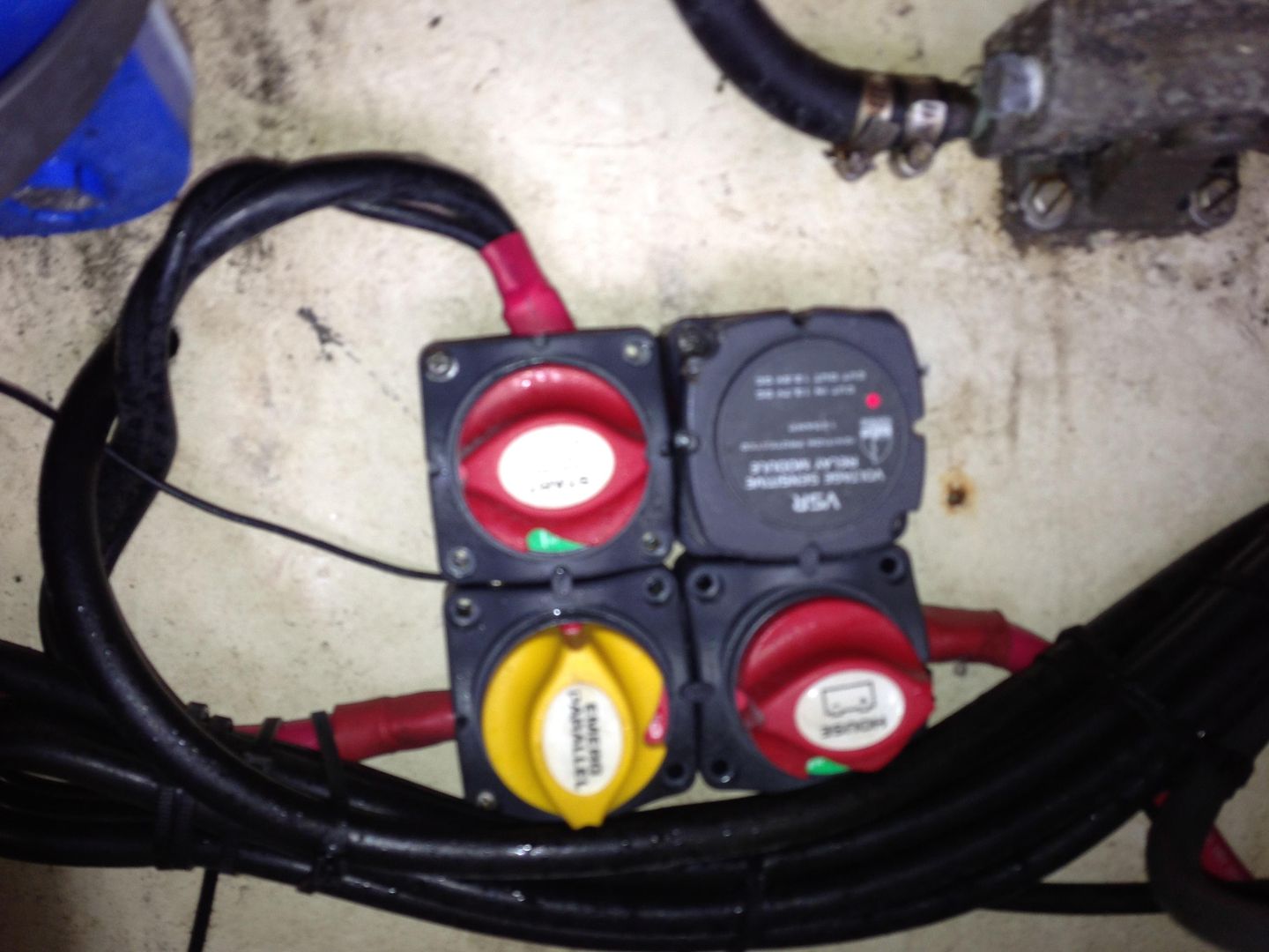
The VSR (but with about 6' of extra cable wrapped back and forth by the installer) :evil:
IMG_0457.jpg
 
First thing you need to do is get some Tilex Mold & Mildew Remover and ****** down all that bilge area.

mold_and_mildew.png
 
These bilge hoses have no high loop in them and should be replaced with the same...But longer hose to form a loop.

The Wing bolts need to go on the batteries.

IMG_0456.jpg
 
Ditto to what Bobby (Warthog) stated. Wing nuts? Really? Really? Really? Really? ... haven't you been reading here a while, haha?

I think after a good and thorough cleaning to could improve the runs and where existing wires are supported. I would probably tackle the clean-up run-by-run, as I don’t see enough evidence for a total rip-out and replacement.

Believe me, less a Cabo yacht or Grady White, the condition under the helm isn’t all that bad. You can make it more orderly and ensure every wire and termination is properly marked. I have one of those Brother label makers where I bought a roll or two of special UV and chemical resistant label tapes … and it works slick! On my rig, every wire is labeled within 8” of its termination and every fuse slot is marked with the device and amp rating.

One thing I note is that no heatshrink or liquid e-tape was put on any connection up at the helm. I’d at least pull aprt a few that had AMPLE length to allow a re-wire, just to check the condition of the wires. If turning brown with corrosion, you have a bigger problem and ALL should be checked. No connection anywhere on that boat used in a marine environment should be connected without being covered by adhesive-lined heatshrink (HS) or liquid e-tape if you can’t or don’t have to take them apart.

In the bilge and in the stern I seal ALL connections with black 3M 5200 covered by adhesive-lined HS.

Remember, like car companies, Parker puts in a generic harness that could have upteem option installed … so you may find lots of ‘dead legs’. Stay with your critical-to-safety circuits first and you’ll get it cleaned up!
 
Thanks guy. Yes, I already know the wing nuts are a no-no. I check them constantly, and they've been on the list for replacement along with this project for a while now. I spent so much time wrenching on the previous OX66 engine that I was just sick and tired of working on the boat and really enjoyed just using it this past season after the re-power. Now its time to get down to business and clean things up for next season.

BTW, that black stain in the bilge is not mold - it is accumulated gunk from 2-stroke oil, since the tank used to sit back there and was apparently often "missed" when being refilled. Thank God its finally gone, but its gonna take a lot of elbow grease to get rid of it - what you are seeing is AFTER repeated washings with Simple Green. When I pulled the tank out last year, there was literally a gallon or two of oil in the bilge. (yes the bilge pump still works - it gets tested before every outing and I give it a "hose test" each time the boat is hauled out)

I think this project will involve two steps:

1. Re-thinking the wiring patterns. For example, I'm not even convinced that the battery setup is correct, since I had a local shop do the work and their work is spotty at times. I want to trace out all the lines, label them, then make sure there is no crossover between battery banks, optimize the run lengths and termination points, and make sure that each run is sized properly for its circuit and isn't longer than necessary (i.e.. the extra 3' of black battery cable simply looped back and forth over the VSR)

2. Re-terminating and organizing EVERY single connection on the boat. As you can see from the pix, there are a lot of automotive type connectors being used without any sort of strain relief, several "piggy back" connectors (spade terminals attached to spade terminals attached to spade terminals attached to a terminal block). I have two of those labeler machines - didn't know you could get chemical resistant tape for them. I'll look into it.

As to the loop for the bilge hose, is it still necessary if the discharge port is about 4" below the gunwale? (e.g. high above the water with nearly no risk of taking in water). I have a loop in the forward bilge exhaust tube, since the discharge port is closer to the waterline. I also want to add a second bilge pump to the back to be safe, since I already have an extra discharge port/through-hull on the starboard side.

Also, another question - I'm not certain that every battery has a circuit breaker within 7" of its main power feed. I think only the rear most house battery does, and it was on the boat when I acquired it. It is not housed in any sort of protected box, and just "floats" in the air a few inches off the battery, IIRC. (its one of those hump-shaped metal and plastic deals with two posts). What product do you guys recommend for the main breaker for each battery? Also, there is no requirement to use one on the starting circuit, therefore if the only connection to the starting battery is the engine, no breaker is required on that battery, right?

Thanks again for all your help - you are helping me to feel that this project is possible. :)
 
warthog5":23wt9ahy said:
Pretty sure I found a problem.

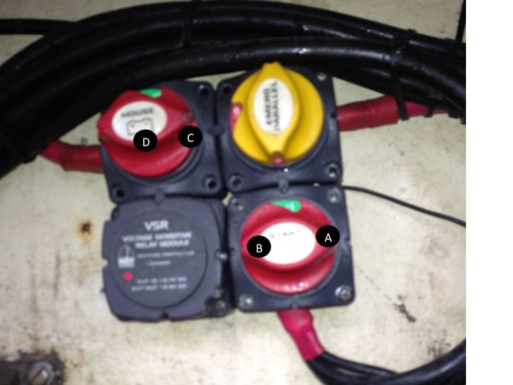
Look at this pix. There is supposed to be NO cable hooked to the Yellow combine switch.

Remember when you look at the schematic....your looking at the back side and looking at the pix your looking at the front side.

http://www.bepmarine.com/media/product/ ... 8082df.pdf

Interesting. The shop wired this for me (I provided them with the diagram). I'll have to actually look at this now and think about it. :)

EDIT: Yup, you are right! Good catch. It actually looks like the thing is rigged COMPLETELY wrong.

If I am reading the diagram correctly, (A) should go to the start battery, (B) should go to the outboard, (C) should go to the House battery, and (D) should go out to the House load.

It appears that the knuckleheads at the shop wired nothing to (A), the outboard starter and charging feed to (B) (which appears correct), nothing to (C), and the House battery to (D) (or perhaps vice-versa). Depending on what post they connected to on the top right (which I assume must be the Start battery), then it is either bridging to (C) (House battery) or to (A)... This might be causing the voltage spikes to the house battery bank when I start the motor.

This is one of the things I despise about having a boat - I cannot find a competent technician in an town with a sizable commercial fleet and a decent sized sport boat community! <Argh>


Slide1.jpg
 
SBH2OMan":mp5v3ww3 said:
Also, another question - I'm not certain that every battery has a circuit breaker within 7" of its main power feed. I think only the rear most house battery does, and it was on the boat when I acquired it. It is not housed in any sort of protected box, and just "floats" in the air a few inches off the battery, IIRC. (its one of those hump-shaped metal and plastic deals with two posts). What product do you guys recommend for the main breaker for each battery? Also, there is no requirement to use one on the starting circuit, therefore if the only connection to the starting battery is the engine, no breaker is required on that battery, right?
On my rig my POS battery connections go direct to the battery switch and the NEG conns go direct to the Ancor Power Post.

The only place I have a breaker is on the main run(s) going to the helm, by a circuit breaker installed into a tupperware box. See posts using search, I've talked about this before. Simple, virtually waterproof [grommetes for the wire entries) and witht he ability to kill the circuit if needed, so REPLACE that stupid OEM auto-type thermal breaker with a real marine breaker that has a toggle switch ...
 
DaleH":8k24wr4s said:
The only place I have a breaker is on the main run(s) going to the helm, by a circuit breaker installed into a tupperware box. See posts using search, I've talked about this before. Simple, virtually waterproof [grommetes for the wire entries) and witht he ability to kill the circuit if needed, so REPLACE that stupid OEM auto-type thermal breaker with a real marine breaker that has a toggle switch ...

Yes, I saw your posts on that. Was wondering if there is a product that already incorporates that tupperware box idea so I don't have to fabricate one. (though I have plenty I could use, I suppose). Would prefer something I can mount to the transom next to the VSR to keep it clear of things.
 
BEP and other places (McMaster-Carr) will sell you a NEMA-rated box for $120 and up ...
 
As to the loop for the bilge hose, is it still necessary if the discharge port is about 4" below the gunwale? (e.g. high above the water with nearly no risk of taking in water).

Famous last words. It's a simple job to fix and be safe.

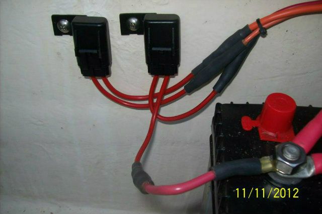
No Breakers on the batteries. However.....There are sealed fuses by each battery to feed power to the bilge pup float switch when the boat is at rest and the Master switches are OFF.

100_4339-2.jpg


This is my setup for the Breaker. That breaker feeds the helm as discussed before.\


100_4067.jpg
 
Back
Top