For those that have re-wired their Parkers...

Classic Parker Boat Forum

Help Support Classic Parker Boat Forum:

This site may earn a commission from merchant affiliate links, including eBay, Amazon, and others.
warthog5":3bfu25jj said:
First thing you need to do is get some Tilex Mold & Mildew Remover and Douche down all that bilge area.

mold_and_mildew.png


Or get Kevin (megabyte) to pay a visit to your boat he will get that baby sparkling. He is probably cringing looking at those pics!
 
Interesting. The shop wired this for me (I provided them with the diagram).

Sounds like Kev's deal when he had the Airmar B60 X-ducer installed.

The shop installed the X-Ducer with the arrow pointing forward and that is the way most other X-Ducers were. But a Tilted Element X-ducer the arrow points at the KEEL and even has the word "KEEL" imbedded in the top of it.

Failure to follow instructions! :(
 
Yes but you want to size it for the load that the House components would put on it and then have the correct size POS & NEG wires running up there. They should be fine from the factory, but let me tell you something about that. That cable in MY boat says Marine on it. But it's SAE [Society Automotive Engineering] It has thicker strans and is NOT tinned. It doesn't flex near as well. I still used it, as it was in good shape. But I did change all the ends.


Interesting. The shop wired this for me (I provided them with the diagram). I'll have to actually look at this now and think about it. :)

EDIT: Yup, you are right! Good catch. It actually looks like the thing is rigged COMPLETELY wrong.

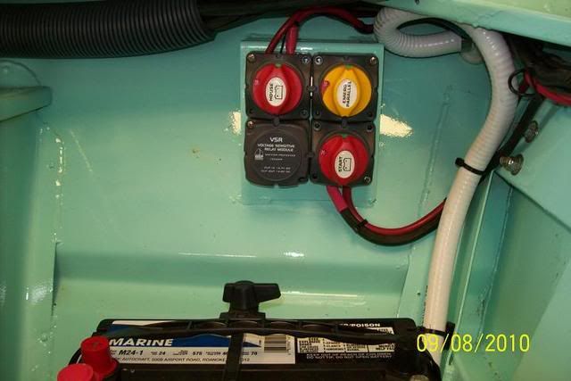
If I am reading the diagram correctly, (A) should go to the start battery, (B) should go to the outboard, (C) should go to the House battery, and (D) should go out to the House load.


When the Cluster switch is looked at on the back side....The terminals are marked to make sure they don't screw up....But they did it anyway, because they don't understand how the thing works. I've installed at least a dozen of them now.

Another thing. The BEP factory uses Automotive connectors. I redo them before a install.

This is one for twin's...But you get the idea.

100_0703.jpg


100_0704.jpg


100_0706.jpg
 
Nice tutorial on the BEP.

Looks like I'm keeping my boat for the time being, that switch is on my list of upgrades, nice to get the "Wart" look at it. :mrgreen:
 
Here is a article I wrote on another forum that I keep Bookmarked. It's to long to rewrite it every time.

It was written around the questions about a Perko switch.

BEP Cluster Switch.

You start your day by turning the Start switch and the House switch to ON.
At the end of the day you turn them both OFF.

It doesn't get any simpler than that. You don't have to remember to turn from Batt 1 when going out and switch to Batt 2 on the way back in. Just something else that you have to remember.

OK so what goes on with it is done all automatically thru the VSR [Voltage Sensitive Relay]

The Relay is in a closed position. As soon as you hit the key to crank the motor the relay opens, due to sensing a large surge of current.

Ok the motor is cranked and running now. The relay is still open. The Alt is charging the Start battery until it reaches a set voltage and charge.

Then the relay closes and is back charging Both the Start & House Battery.

Now another feature that happened when you hit the key is your electronics were ON and wired from the House battery. This will stop any spiking of the Electronics. They don't like to be spiked!

OK...Now your out sitting on the beach. The motor is OFF, but you have the Radio playing for hours. The Relay senses the drop and opens the relay again. The radio is still playing, but the relay just disconnected the Start battery out of the circuit so that it stays at Full charge to start the motor.

When you get ready to leave the beach and crank the motor the alt will charge the Start battery first and when it's back up, the relay will close and charge the House battery.

There is one more switch on the Cluster. It is the Combine switch. Think of that as Jumper Cables without having to dig them out and hook them up. This switch would normally be in the OFF position, until you need a boost on the start battery. Then turn it to ON. After the motor is running turn it back OFF.

Everything is all Automatic. No thinking about it. Your batteries will have a much better charge in them.

The unit pictured above is just slightly larger than a Perko switch. So it doesn't take up much room and takes a LOT less room than the Blue Seas version. It looks cleaner too, due to the cables that are needed on the Blue Seas version.

The cost is aprox $150 for a unit for a single outboard and 2 batteries.


100_2497.jpg


100_0706.jpg


100_1263.jpg
 
Thanks Warthog, that sums up the reason I bought one for the boat when we repowered. Too bad the installer screwed up my plans. :evil:

Any advice on a good (enough) crimper? I want the right tool for the job, but I'm not going to spend $400 to $1,000 on a fancy pair that I'll use for one project and then once or twice a year after that.

I'm wondering if something like this would do the job (I plan to only use insulated heat-shrink terminals, so a double crimper is no good))

http://www.amazon.com/Astro-Pneumat...changeable+Ratchet+Crimping+Tool+Set,+7-Piece

Or should I get two of these (one for 8-16 and the other for 10-22)
http://www.delcity.net/store/16!8-Gauge-Insulated-Terminal-Ratchet-Crimp-Tool/p_10430
 
This is the one I have.

http://www.delcity.net/store/Insulated- ... l/p_793366

You will note that most crimpers do not have the 8ga in them...They stop at 10ga. This one has the 8ga in it.

Yes it's expensive, but I use mine all the time.

Now for Battery cables this one is the cheaper desired unit.

http://www.delcity.net/store/Heavy-Duty ... er/p_10383

I don't have that one.

I bought this one a Loooooong time ago before the price was this outrageous.

http://www.westmarine.com/webapp/wcs/st ... MCksYZIXtk
 
I acutally prefer the 'hammer' powered crimpers for heavy cables and find one good solid hit with a small sledgehammer works better to form a good crimp than many multiple hits from even a 160z ball peen hammer ...
 
That is classic.

I think I'll mark the cables and then just take them somewhere to have them crimped. I can't see spending the money on a tool I will likely use 2x every 5 years or so...

On the other hand, I just ordered one of those crimpers from Delcity - thanks Warthog. Also buying up supplies of cable ties, mounts, heat shrink and terminals.

I'm mulling over options for labeling the wires and ran across this:
http://cgi.ebay.com/ws/eBayISAPI.dll?Vi ... 0959081255

Very tempting, considering that it is selling for less than the combined value of the tape cartridges... But I may be getting a little "tool happy" and could probably get by just fine with white heat shrink that I write on with a fine tip Sharpie..
 
Do you guys ever use braided sheath or corrugated wire loom? I sure like the looks of a job finished with braided sheath, but it makes it difficult to add anything in the future without re-doing the whole job (unless I leave a pull cord inside each sheath)
 
I guess ease of access trumps "show car" looks. :)

Here's another question for the experts... I'm adding up all the amp draws and verifying the wire sizing, fuse/circuit breaker requirements and I've run into a "best practice" type question.

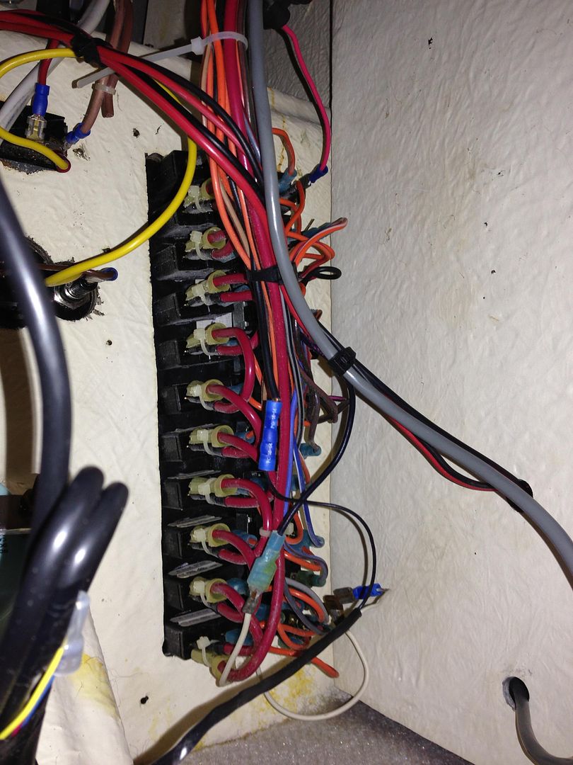
I notice that Parker chose originally to wire a single power feed (looks like maybe an 10 AWG wire?) to the switch panel and then jumper from one circuit to another - you can see it in this photo:

IMG_0421.jpg


However, when I add up the current draw of all the devices that are currently connected to this panel, they add up to 60 amps at their respective mfgr ratings. Looking quickly at my wire sizing chart, I see that a 50' run of wire drawing 60 amps (and really it should be sized for 50% more, right?) is 4 AWG. Uh..Houston, we have a problem... Unless I'm missing something, since each of these circuits is essentially sharing a common power feed, then at the very least the first connection coming from the battery should be a 4 AWG wire (which it is not!).

Should I re-wire this panel so that each is drawing its power independently from a power bus supplied by a 4 AWG cable and then size the wires for each independent circuit? I'm a little confused about the way Parker has this wired - in theory, if you flip everything on all at once, it would overload the power supply to the panel...
 
Here's a schematic I'm working on showing the power feeds broken out onto a separate bus bar rather than wired in parallel like they are in the factory setup.


Comments/suggestions welcome. (Note the wiring on the bilge pumps - my thinking is to have a "manual override" to bypass the float switches for periodically testing the motors and in case of float switch failure.
 

Attachments

  • Visio-LoriK Wiring.pdf
    30.3 KB
SBH2OMan":2lfpmtil said:
Note the wiring on the bilge pumps - my thinking is to have a "manual override" to bypass the float switches for periodically testing the motors and in case of float switch failure.

The 'manual over-ride' you speak of, is how the factory wires them.
The switches on the helm control the forward and the primary rear pump, bypassing the float switch.
The factory only installs a single rear pump, so if you have a backup pump back there, it will not have a switch (unless someone wired it that way).

You should be able to flip the helm switch(es) and hear the pump(s) run.
If it doesn't, someone has either disconnected or 're-wired' something.
 
It is also why I like this Float switch.

RUL-40A_lg.jpg


It's hard to see in the pix, but just over top of the grommet that is up against the body of the unit is a little handle sticking out. By pushing that down you elevate the float like there was water in the bilge and this tests your circuit.
 
Back
Top