For those that have re-wired their Parkers...

Classic Parker Boat Forum

Help Support Classic Parker Boat Forum:

This site may earn a commission from merchant affiliate links, including eBay, Amazon, and others.
Sometimes you just have to rip it out and start over, if for nothing else than to know it's done right.

FWIW... When I worked on an airfield, stuff that could get sucked into an aircraft engine or puncture a tire was called "FOD" (foreign object damage).
FOD in a boats bilge can find it's way to the bilge pump and totally ruin your day. :shock:
As you discovered, old zip-ties and hardware make their way into the pump and can cause a catastrophic failure, and it will always happen at the worst possible moment.
 
First, if you are in the water, you need to pull the boat and address that seacock. That is a timebomb in my opinion.

Especially with that new Honda, hate to see it go under.

It looks like you have the wiring under control.

For cleanup I would suggest a 30-40% beach and water mixture in a spray bottle to take care of the mold and dirt in the bilge and under the hatches. I claen my boat like that onece or twice a season, really keeps the mold under control.
 
Bryan 2530":2u2c50q1 said:
For cleanup I would suggest a 30-40% beach and water mixture in a spray bottle to take care of the mold and dirt in the bilge and under the hatches. I claen my boat like that onece or twice a season, really keeps the mold under control.

These days, bleach comes in a 3 quart bottle.
I put one bottle of bleach plus 1 quart of water into a 1 gallon pump sprayer and use it in the bilge and under the washboards.
75% bleach and 25% water.
Works for me.
 
Bryan 2530":49ll3yy7 said:
First, if you are in the water, you need to pull the boat and address that seacock. That is a timebomb in my opinion.

Especially with that new Honda, hate to see it go under.

It looks like you have the wiring under control.

For cleanup I would suggest a 30-40% beach and water mixture in a spray bottle to take care of the mold and dirt in the bilge and under the hatches. I claen my boat like that onece or twice a season, really keeps the mold under control.

Thanks Bryan. I'll probably pull it once I can start it again. :D

As to the "mold" - believe it or not, there is no mold in there. It is all 2-stroke residue. Unfortunately I don't think this bilge will ever again be white and shiny, but it sure looks a lot better without the 1/8" thick varnish of old 2-stroke oil!
 
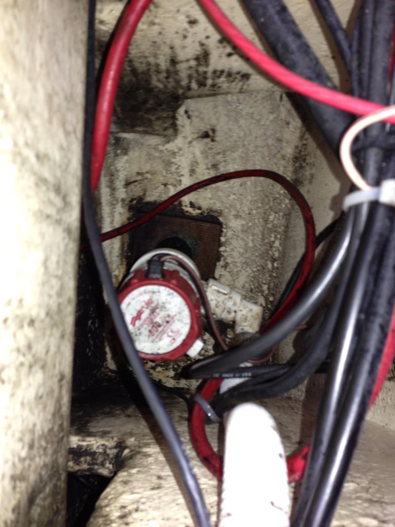
There were probably 5 or 6 pieces of cut-off wire ties stuck in the strainer of the bilge pump

That's dangerous.

is it OK to have a single common ground throughout the boat or does each battery bank need to have its own ground system?

All the GND's are tied together. Go back and look at the BEP wiring diagram.

And Yep....I would not be able to sleep knowing about the Seacock. It should be removed, cleaned and rebed it.
 
warthog5":97yiptw9 said:
There were probably 5 or 6 pieces of cut-off wire ties stuck in the strainer of the bilge pump

That's dangerous.

is it OK to have a single common ground throughout the boat or does each battery bank need to have its own ground system?

All the GND's are tied together. Go back and look at the BEP wiring diagram.

And Yep....I would not be able to sleep knowing about the Seacock. It should be removed, cleaned and rebed it.

Thanks.

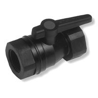
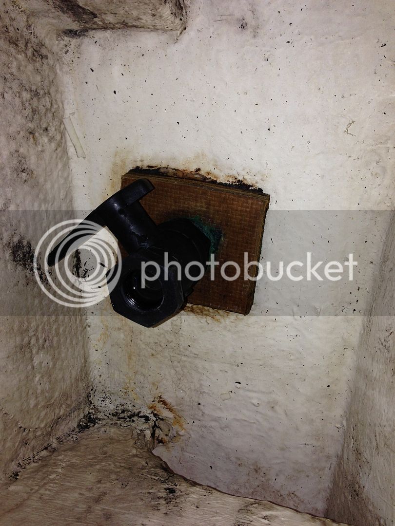
After re-reading my earlier posts, I should clarify that it was not the through-hull that is turning, but rather the ball valve that is screwed to it. It appears that the assembly is a plate of wood and flush against it is a plastic fitting, part of which is a valve like this one:

00001450.jpg


There was a bit of efflorescence around the base against the plate of wood, so I'm assuming there is a bronze through-hull/strainer which comes up through the hull and has male threads to which this valve assembly is screwed. There are NOT three screws in a triangle pattern like you see on one-piece seacocks. I know for sure there is a bronze strainer, because I have inspected it from underneath while the bottom was being resurfaced. FWIW, I asked the shop that did the bottom paint back in September to inspect the through-hull and make sure it was well bedded (they told me it was fine). Unlike the shop that did the wiring work, the shop that did the bottom paint has a very solid reputation for good work.

So I think what happened (if I am right) is that the bronze through-hull is securely in place, but the plastic valve assembly rotated while I was trying to remove the livewell pump. You can see a picture of what it looked like before I pulled it apart here:

IMG_0453.jpg


And afterwards here (not a very clear picture, sorry)

null-24.jpg
 
So I think what happened (if I am right) is that the bronze through-hull is securely in place, but the plastic valve assembly rotated while I was trying to remove the livewell pump.

OK That is a little different. :)

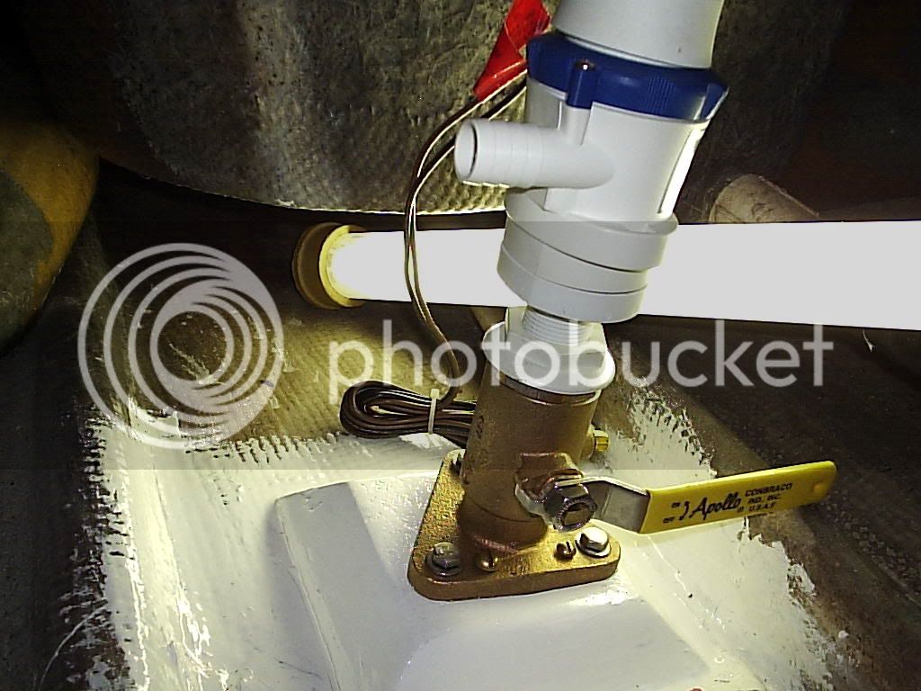
You have a Scoop, then a Ball valve and then the pump. Phenolic or a piece of Coosa board is a better substitute for the wood, unless you take the time to do one like this.

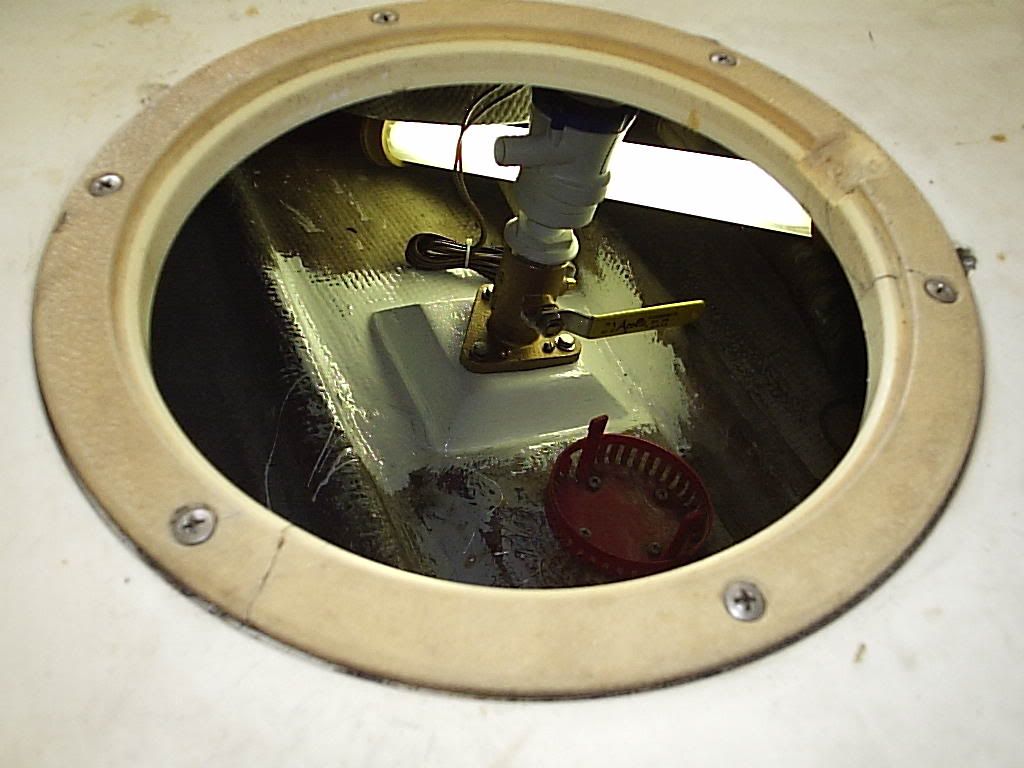
It was all mocked up dry....The scoop threads were cut off. It is noted where the handle would be and the fasteners would land also once it was tightened up. The outer surface was covered with fiberglass and then bonded to the inside of the hull.

100_0896.jpg


Another thing that could be done is go to the grocery store and get a square tupperware container. The size that would hold a sandwich. This is your mold. This would be a good first time project for those that have never messed with fiberglass. Cut many many layers of glass to fit in that mold and laminate them to build a thickness of aprox 3/4in. Use that for your block.
 
Thanks WH - I am learning a lot from looking at the way you put things together. I really like the way you drill the over-sized holes, then fill with what must be epoxy, then you can put your pilot holes into the epoxy rather than wood. Very cool.


Here's another set of questions for you guys (Thank you!):

  • 1. I noticed that when I pulled the batteries, NONE of the connections were to the main posts - they were all to the small posts (I think they are 5/16" right?). Is there any reason not to use the regular large battery terminals for the main connections? (tying the grounds together with a "flag" type, the starter connection, etc)

    2. If I have three or four accessories inside the transom that need to be fused, should I just get some sort of water proof fuse box that will hold ATC fuses instead of using the inline Ancor 607019 units?

    3. Is there a "default" size for terminating battery terminals on bus bars and accessory terminals? I notice that terminals come in 1/4", 3/8", and 5/16" sizes. The stuff that is on there now is all really random, it seem.

    4. Is there a reason to use those "Power Posts" instead of a regular 10-terminal bus bar if I have the room?

    5. Do you guys like the covered dual bus bars, or do you like to separate the positive and negative bus bars?

    6. What brands/models of bus bars do you guys like? I like the covered ones, but the only covered one from Blue Sea is 20 terminals and I don't need that many connections.

Thanks!

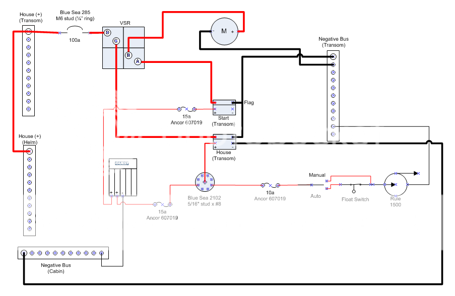
Here's my current working draft for the work inside the transom. I think I'll be abandoning the second house battery.

Transom-1.png
 
. If I have three or four accessories inside the transom that need to be fused, should I just get some sort of water proof fuse box that will hold ATC fuses instead of using the inline Ancor 607019 units?

Blue Sea makes a 6 position ATO type fuse panel - with neg bus or without. I have used these and they are work well. They are NOT waterproof. Mount high on the transom and shield from direct water contact. The have a cover that protects the terminals from accidental shorts.

4. Is there a reason to use those "Power Posts" instead of a regular 10-terminal bus bar if I have the room?

Power posts and distribution bus bars are AMP rated. Power posts are often used in dedicated high amp circuits - windlasses, starting, winches, etc. Multi-terminal bus bars in lower amp circuits - typically house loads - lights, bilge, bait, RWD pumps, etc.
 
Mike S":1gqtay2c said:
4. Is there a reason to use those "Power Posts" instead of a regular 10-terminal bus bar if I have the room?

Power posts and distribution bus bars are AMP rated. Power posts are often used in dedicated high amp circuits - windlasses, starting, winches, etc. Multi-terminal bus bars in lower amp circuits - typically house loads - lights, bilge, bait, RWD pumps, etc.

Thanks Mike - I was actually referring to those Power Posts that have a single large terminal in the center, surrounded by 8 #8 screws in a circle around it. Like this one:

201465.jpg


It seems like they'd be good in a really tight spot, but a bit messy, since the connections will be radiating outward in a circle, as opposed to a nice neat bus bar where all the connections can come back in a straight line.
 
It's hard to make clean installs with those. It's just the way the wires flair out from it all over.

201465.jpg
 
OK guys, here's an update based on a couple hours spent poking around again today...

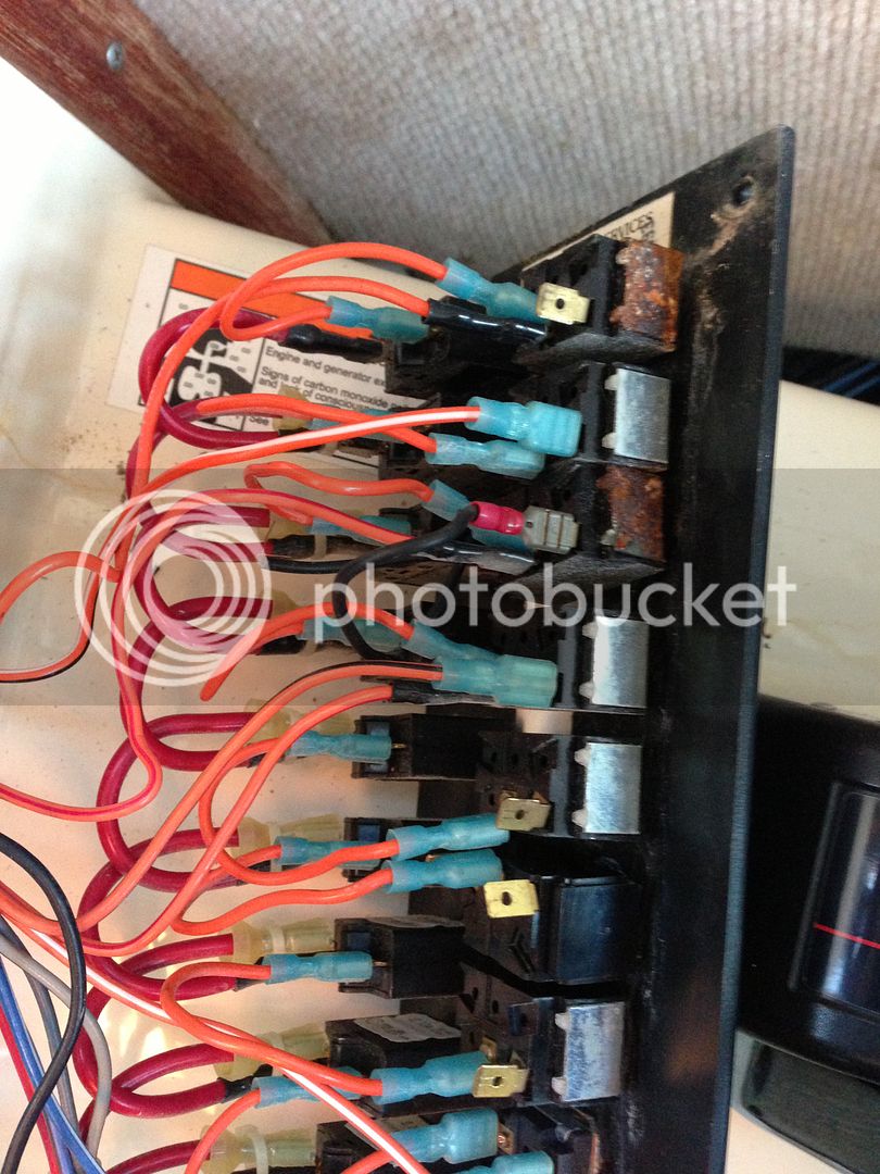
I pulled the switch panel and found some rusty switches (photo is upside-down):
IMG_0561.jpg


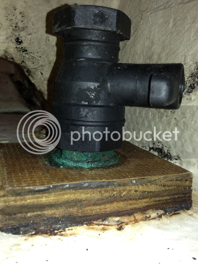
Got some close-up shots of that seacock:
IMG_0545.jpg

IMG_0555.jpg


You can see the efflorescence (blue color) at the base. I'm assuming this is from a bronze through-hull/scoop strainer. Should it be bonded if the surfaces in the water are completely coated with bottom paint?

After my investigation today, I've decided to keep the second house battery in the cabin with an existing run of 2 AWG wire to it from the first House battery in the transom. Based on my ampacity charts, this gives me enough for a 120 amp draw, which should be more than plenty.


For you tool heads out there, I just could not bring myself to create battery terminal crimps with the hammer-style Ancor unit my slip neighbor loaned me, so I bought one of these:

http://www.kljack.com/default.aspx?page ... de=ET50116

contentonly.aspx


When I'm done, it will be up for sale for a discount. :)

I think I am done with my explorations and have my final list of parts and my plan. I'm cleaning up a lot of wiring that was messed up by the PO as well as some dodgy stuff that looks original (like non heat-shrink terminals).

I'd like to replace the factory switch panel - does anyone have recommendations for something that will hold 12 circuits and fit in a 5" x 12" space? (the cut-out is 3.25" x 10.25")
 
You posted some good pix's that time that show vivid detail...That's what we need.

I take it this boat sits in the water? If it does...The thru hulls need to be bonded and that is why your getting all that Green on the scoop.
It needs attention. All Bronze and or a way to bond to the scoop. I don't know how without adding more Bronze pieces.

--------------------------------

Your drawing:

You have gone crazy with Buss bars. There is a NEG buss bar behind the helm with 20 screws on it and then there is a 10 or 12 terminal buss bar in the bilge area in my boat. That's it.

All those POS buss bars I don't understand?
 
Thanks - yea, those bus bars are just placeholders until I count up how many connections I actually need. As it turns out, I won't need a POS bus bar for the transom area, and probably not one for the helm (up there I'll use a dual bus fuse box).

Yes, the boat currently lives on the water (and has most of its life, AFAIK. There is no bonding screw on that through-hull fitting, so I guess the next time its out of the water, I'll have to just replace the marelon assembly with a bronze unit. Is it possible to get one of those "flange type" units and thread it onto the existing through-hull, then screw it down to that "board" or whatever that material is? (now that I have a close-up photo, I can see that it is not plywood).
 
Is it possible to get one of those "flange type" units
and thread it onto the existing through-hull, then screw it down to that "board" or whatever that material is?

Yes but it's a lot easier when you can remove the scoop.
That long thread will need to be cut shorter. How much shorter? I don't know exactly. You take the scoop and thread the seacock on to it. Then measure.

You mock it up dry in the boat with the backing board in place.

You want it to look like this.

seacockdone.jpg


seacockdone2.jpg


Note the bonding screw on the seacock flange
 
Back
Top